Overview
The circuit was designed to create an auto fade circuit that will be
used to provide a mechanism of bringing the voice on top of playing
music.
Terminology
TL072 – a low noise JFET input operational amplifier with features such
as common-mode input voltage range, high slew rate, operation without
latch up, compensated internal frequency, high input impedance at the
JFET input stage, low noise, low total harmonic distortion, protected
from output short circuit, low input bias and offset currents, wide
common-mode and differential voltage ranges, and low power consumption
* 4011 – a quad 2-input NAND gate integrated circuit, generally
characterized by small fluctuation in voltage supply, very high
impedance, outputs that can sink and source, one output can drive up to
50 inputs, high speed gate propagation time, high frequency, and low
power consumption
* 4066 – a digitally controlled quad analog switch utilizing advanced
silicon-gate CMOS technology with features such as individual switch
controls, matched switch characteristics, pin and function
compatibility, low quiescent current, low ON resistance, wide analog
input voltage range, and 15 ns typical switch enable time
Circuit Explanation
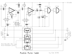
The operation of the circuit is built about the function of amplifier
IC1A that strengthens the signal of microphone by regulating the gain of
the unit depending on the needs. The intensity of the sound is adjusted
by the potentiometer RV1, which is fed via pins 9 & 10 to the two
switches of IC3. The switches are possessing resistance of 10M ohms when
no excitation is present while a resistance drop to 300 ohms occurs
during excitation which allows the signal to pass through. When the
signal reaches a specified level, due to additional strengthening of
IC2B via RV2, it will be rectified by D1 & D2.
An interrupted DC signal is produced by the circuit in the pattern of
IN1 signal and this is being used to change the operation of IC2A and
IC2B. The stereo signal can pass when IC3A and IC3B are turned ON. When
the input of J1 contains audio excitation, the operation of IS2A &
IS2B will change that affects the state of IC3, causing the switch A-B
to open and C-D to close. The stereo signal is interrupted and allowed
to flow from the input of J1. The circuit can be tested by using placing
a musical program in the input of J2 & J3, which passes to the
outputs of J4 & J5, without distortion or reduction of signal for
the two channels. The use of capacitor C5 is to pass the signal of
microphone when the signal reaches a certain point. The circuit will
vibrate as the speech is done.
Part List
R1-2= 1Mohms
R5-6= 1Mohms
R3= 150Kohms
R4-8= 1Kohms
R7= 220Kohms
R9= 470Kohms
C1-6= 220nF 100V MKT C2= 100pF ceramic
C3= 1uF 25V
C4= 47uF 25V
C5= 10uF 25V
C7-8= 100nF 100V MKT
C9-10= 4.7uF 25V
D1-2= 1N4148
IC1= TL072
IC2= 4011
IC3= 4016 - 4066
J1-2= RCA Famale Plung
RV1= 47Kohms Log. pot.
RV2= 47Kohms Lin. pot.
All Resistors are 1/4W 1-5%
Application
Auto fade is intended for voice over stage where one needs to fade the
background audio during the presence of several voice sections. This
circuit gives advantage to radio station disc jockeys and for
announcements made on top of music in malls to call the shopper’s
attention, in hospitals, in airports, and other establishment.
Source:users.otenet.gr/~athsam/audio_auto_fade.htm

No comments:
Post a Comment