
Features
LED dot matrix display 40x7;
- Display of clock, calendar, inside and outside temperature, text messages;
- Automatic Daylight Savings Time;
- Capability of keeping the real time clock working correctly for more than one week
without power supply;
- Inside temperature measurement (0 ÷ +75) °C, ±0.5 °C accuracy;
- Outside temperature measurement (-40 ÷ +75) °C, ±0.5 °C accuracy;
- Supports static and running messages with different effects;
- Full Cyrillic and special symbols supports;
- Memory for 10 messages, each including up to 250 symbols;
- Automatic brightness control;
- IR remote control for settings messages select;
- Power supply: 12 ÷ 24V DC;
- Front panel dimensions 305 x 69 mm.
Schematic description

The core of the device is microcontroller PIC18F252 (U9). It controls all the functions of the device, generates the overall algorithm to control the LED matrix. LEDs are connected in matrix 40x7. The columns tie together the cathodes of the LEDs and rows tie the LEDs anodes. The LED matrix is controlled dynamically in row by row. To safe space and number of components, the LEDs are driven with specialized LED driver STP16CP05 (U101-U103), produced by ST Microelectronics.

There are 7 cycles to display each row plus an extra blank cycle, used to process temperature measurements. Thus, the refresh rate of the display is 125Hz. To control the display brightness is used the "outputs enable" (OE) pin. Each row cycle begins with logical 0 on the OE pin (outputs are enabled). The duration of an enabled signal changes depending on the desired brightness, using the microcontroller's on-chip PWM module.
You should note that numbers of columns and rows are not sequential to the corresponding pins of the ICs (U101-U103). This aims to simplify the design of PCB. The LEDs' corresponding bits are rearranged by software to fit with their physical order.

Real-time clock / calendar
The real time clock is implemented with U10 - PCF8583. This is a clock / calendar / alarm circuit with I2C interface and on-chip 32768Hz oscillator. The PCF8583 contains all necessary counter registers to provide real time clock and date information. Its power consumption is very low (typical supply current is 10 A). It operates in wide range of supply voltage from 1 to 6V. These features will make it possible to have a real time clock available for a long time using a small lithium battery or even a back-up capacitor. The designed PCB provides both options.
The footprint for lithium battery is suited for 2032 type socket. The experiments using 1F backup capacitor show that the clock remains active more than a week after turning-off the power supply. The diodes VD10, VD11 and VD12 should be Shotkey type as shown in the scheme because of their low drop forward voltage. Trimmer-capacitor C21 is used to adjust the oscillator frequency at 32768Hz. For I2C communication is used the Master Synchronous Serial Port (MSSP) module in PIC18F252. This module is set in I2C master mode. On the same bus an external EEPROM (U11) can be connected to expand the capacity of the data storage. The present version of firmware does not need an external EEPROM, so it can be omitted.

Temperature measurement
For ambient temperature measurement are used LM35 sensors (U5, U6). They are factory calibrated directly in ° Celsius. The output response is 10mV/°C. The supply voltage should be between 4 and 30 Volts. To make a full-range temperature measurement, a negative voltage must be applied to the output through a resistor (R4 and R5). To ensure this requirement, the ground pins of the sensors are connected to the analog ground through two diodes (VD4,VD5 and VD6,VD7), which pick them up with approximately 1,4V.
In that case the Vcc (+5V) power supply is not enough for LM35, so additional voltage regulator U1 (78L09) is needed to be used. The signal from the sensor is taken between the output and the negative pins of the LM35. The voltage between these two pins is bipolar with polarity depending on the measured the temperature sign. The sensors could be connected with external three-wire cables. Software is designed to show inside temperature from U6 and outside temperature from U5.
A/D converter

Its output value needs to be adjusted at 2,55V using a trimmer-potentiometer RP1. VD8 and VD9 are used for temperature compensation. The MCP3302 has an SPI interface, using four signal lines. These lines are under software control from the microcontroller (U9). To ensure accuracy the analog ground is separated from the digital using small ferrite beam (L6). This is an SMD type Z600 ferrite beam in 0805 package. The same type is used to decouple the power supply for A/D converter and for temperature sensors and reference voltage (L4 and L5 respectively).
Brightness control
For an automatic brightness control is used a light-to-voltage converter - U8 (TSL257). Its output voltage is directly proportional to the light intensity on the built in photodiode. The voltage from the light sensor is measured using an on-chip microcontroller ADC. The ADC value affects the PWM module from where the LED panel changes its brightness. To avoid unwanted blinks of the display, a slight software delay of the PWM control is applied.
Display functions
The display settings are adjusted from the user with three local buttons S1-S3. The meaning of these buttons is as follows: S1 - UP; S2 - DOWN; S3 - SET.
Clock settings
To enter in settings mode press once SET button. A "Settings" label appeared on display. To set the clock and date, press UP or DOWN buttons to select "Set time". Press the SET button again and display will show the current time, where the hours' digits are blinking. Use UP/DOWN buttons to adjust the correct hours. Then press SET to select minutes. After the minutes are set, the display will switch to date adjustment. Adjust date, month and year and press SET to finish. The software automatically calculates the day of the week.
If an incorrect date is selected (for example 29.02.10), the display will show an "ERROR" message for a while and will return at the beginning of the date adjustment. When the date is set correctly the display will show a new set clock with blinking "OK" and will wait to confirm the new clock/date values. If the UP button is pressed again the display will ignore the new values and returns at "Settings" mode. If the DOWN button is pressed the display will return at the first step of the "Set time" procedure. When the button SET is pressed a new clock and date value are accepted, seconds are reset and display will run in normal mode. The software automatically switches on Daylight Savings Time (+1 hour). It happens on the last Sunday in March, at 3:00 o'clock a.m. Return to winter-time (-1 hour) is done on the last Sunday in October, at 4:00 o'clock a.m.
Brightness settings
The user can select the brightness level in 8 steps or select an auto mode. To change the brightness from "Settings" menu, select Bright and press SET. The display will show the current bright level (from "Bright 1" to "Bright 8") or "Bright A" for auto mode. The desired value is selected by pressing the buttons UP and DOWN. When the SET button is pressed again, the selected value will accept and store it in EEPROM. To exit from "Settings" menu and return in normal mode of display press SET button, when a label "Settings" appears.
IR remote control
An additional feature of the device is the possibility to change settings using an Infrared remote control. It allows the device to be installed on a place with difficult access. The decoder is implemented with microcontroller PIC12F675 (U52) and designed to work with a standard TV remote control, matching RC5 protocol. This protocol is supported from TV Philips.
The decoder received a demodulated digital signal from IR receiver TSOP1736. The software decodes the received command and transmits it to the main microcontroller U9 over an asynchronous serial connection. The LED VD51 blinks once at each recognized command. The main microcontroller (PIC18F252) receives commands from IR decoder using its hardware Universal Synchronous Asynchronous Receiver Transmitter (USART) module. Because the same module is also used for a RS232 connection to the PC, the RX signal is multiplexed between the U52 output or U71 (MAX232) output. Switch is implemented by the 4 NAND elements in U53 (74HC00). Unfortunately, the present version of the firmware is not ready to control a RS232 communication. So for that moment U71, U53, J71 and their adjacent elements can be omitted.
The available buttons from TV remote control are as follows:
- PROGRAM UP - equivalent to local button S1 - UP;
- PROGRAM DOWN - equivalent to local button S2 - DOWN;
- MUTE - equivalent to local button S3 - SET;
- MENU - equivalent to local button S3 - SET (not working with all remote controls);
- Direct buttons from 0� selects predefined messages. From messages 1 to 4 display will show static message of clock, date, outside and inside temperature, respectively. From 5 to 9 and 0 the display shows all available data with different effects.
Power supply
The device needs three different stabilized supply voltages: Vcc (+5V) for main part of scheme, Vled (+2,5V) for LEDs' anodes and a +9V for temperature sensors. For high-efficiancy Vcc (+5V) and Vled (+2,5V) are provided using a step-down regulator. For a +5V is used U2 (LM2575-5.0) and for Vled is used U3(LM2576-ADJ). Because the consumption from the +9V is very low, it is implemented with low power version of standard linear regulator 78L09. Vth1, VD14 and R18 realized overvoltage protection. If the voltage of Vcc exceeds the zener diode voltage plus thyristor gate voltage the thyristor starts to open and gives short circuit Vcc to ground. This protects all the integrated circuits from accidentally raising the supply voltage.
The external power supply must have a fuse or current limiter. Of course, this protection circuit is not necessary, but strongly recommended, especially at the stage of testing. Other two power supplies are not so critical if the voltage is increased. The LED drivers' outputs can work with
up to 20V load and limits the current through the LEDs. The ICs LM35 and LM336 can also work with higher than 9V power supply. It is necessary to pay attention to the Vled voltage. Its value is very important due to the power dissipation in the LED drivers. In this case are used super bright red LEDs dot matrix modules 5x7 (TC20-11SRWA). The LED forward voltage Vf is 1,85V at 20mA. It won't be a problem
to use other type of LEDs. For reliable work the Vled should be 0,5-0,7 higher than the Vf. But not more higher, because the power dissipation in the drivers will increase and the thermal shut-down protection will be activated. To calculate the Vled is used the next formula:
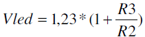
where R2 is between 1 and 5 kOhm. It is also needed to choose a proper value for LEDs current. The current is set with R115, R116 and R117 resistors, connected to pin 23 (R EXT) of LED driver. The showed value (270Ohm) sets a current of approximately 80mA per output. Because the duty cycle of each row is 1/8, the average current through the LED is 10mA. See the STP16CP05 datasheet for output current resistor set. For convenience of changing these resistors, the footprints of R115 and R116 are duplicated next to R117, named R115' and R116'.
In conclusion
Any special adjustments are required to start the device. If it is assembled properly and two microcontrollers are programmed it will immediately start running. U9 can be programmed with one of the two available connectors J4 or J4A depending on the programmer type. It is possible to need to disconnect the Vcc from U9 during programming. For that purpose JP1 is provided. The U52 must be programmed externally.
Please note, that the two double row connectors connecting the two boards are SMD type. The clearance between the pins is 2,00mm, not 2,54!

0 comments:
Post a Comment